- E-TYPE - Electromagnetic clutch without bearing
- G-TYPE - Electromagnetic clutch with bearing
- B-TYPE - Electromagnetic brakes
When assembling, the stator body must be accurately centered on the input drive hub; otherwise, the hub may rub on the stator body and cause damage to the clutch.
Depending on the size of the clutch, the installation must provide for an air gap of between 0.2 and 0.5 mm between the drive hub and the armature disc.
If a SUCO output drive hub is not used, it is important to ensure that there are clearance holes to accommodate the rivet heads when installing the armature disc. The armature disc is centered by the screws which hold the return spring to the output component. When the armature disc is installed, it must remain free to move axially against the return spring.

Construction and mode of operation
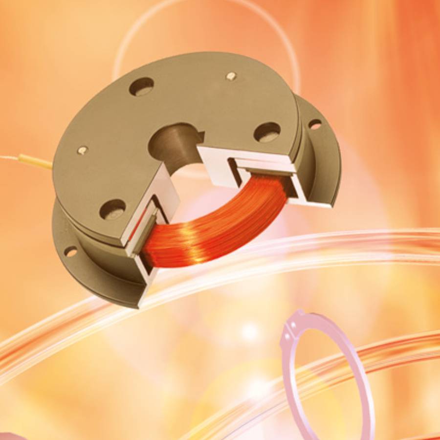
The basic model of the electromagnetic clutch without bearings consists of
- stator body with cast-in coil and
- connection cable,
- the input drive hub and the
- armature disc to which the
- return spring is riveted.

Model A
Clutch with input drive hub
Basic version without output drive hub.
Connection to output side by screws.

Model C
Clutch with input & output drive hub
Basic version with axial output drive (shaft – shaft).

Performance data and dimensions
| Size | E02 | E03 | E04 | E05 | E06 | E07 | E08 | E09 |
| Torque [Nm] For reference purposes 1) | 1.0 | 4.5 | 8.0 | 20.0 | 38.0 | 80.0 | 150.0 | 280.0 |
| Speed of rotation max. [rpm] | 10.000 | 8.000 | 6.000 | 5.000 | 4.000 | 3.000 | 3.000 | 2.000 |
| Power [W] T = 20° C | 9 | 12 | 20 | 23 | 32 | 40 | 55 | 72 |
| d max. [mm] 2) | 10 | 20 | 25 | 30 | 40 | 50 | 70 | 80 |
| D [mm] | 60 | 80 | 100 | 125 | 150 | 190 | 230 | 290 |
| L1 [mm] | 26.5 | 28.0 | 31.0 | 36.0 | 40.5 | 46.5 | 55.4 | 64.0 |
| L2 [mm] | 38.5 | 43.0 | 51.0 | 61.0 | 70.5 | 84.5 | 103.0 | 119.0 |
| B [mm] | 52 | 72 | 90 | 112 | 137 | 175 | 215 | 270 |
| F [mm] | 42 | 63 | 80 | 100 | 125 | 160 | 200 | 250 |
| H [mm] | 29 | 46 | 60 | 76 | 95 | 120 | 158 | 210 |
1) Depending on design of installation, operating and ambient conditions
2) Keyway to DIN 6885/1
Depending on the size of the clutch, the installation must provide for an air gap of between 0.2 and 0.5 mm between the drive hub and the armature disc.
If a SUCO output drive hub is not used, it is important to ensure that there are clearance holes to accommodate the rivet heads when installing the armature disc. The armature disc is centered by the screws which hold the spring disc to the output component.
When the armature disc is installed, it must remain free to move axially against the return spring.
Construction and mode of operation
The basic model of electromagnetic clutch with bearing consists of
- stator body with cast-in coil and
- connection cable, the
- input drive hub with support bearing, and the
- armature disc to which the
- return spring is riveted.
Because it contains a bearing, it is not necessary to center the stator body on the input drive hub when using this model.

Model A

Clutch with input drive hub
Basic version without output drive hub.
Connection to output side by screws.
Model C

Clutch with input and output drive hub
Basic version with axial output drive (mounted on one shaft).
Output drive hub with bearings.
Model D

Clutch with input & output drive hub
Basic version with axial output drive (shaft – shaft).
Performance data and dimensions
| Size | G03 | G04 | G05 | G06 | G07 | G08 | G09 |
| Torque [Nm] For reference purposes 1) | 4.5 | 8.0 | 20.0 | 38.0 | 80.0 | 150.0 | 280.0 |
| Speed of rotation max. [rpm] | 8.000 | 6.000 | 5.000 | 4.000 | 3.000 | 3.000 | 2.000 |
| Power [W] T = 20° C | 12 | 20 | 23 | 32 | 40 | 55 | 72 |
| d max. [mm] 2) | 20 | 25 | 30 | 40 | 50 | 70 | 80 |
| D [mm] | 80 | 100 | 125 | 150 | 190 | 230 | 290 |
| L1 [mm] | 41.0 | 45.0 | 52.0 | 56.5 | 67.0 | 75.4 | 90.0 |
| L2 [mm] | 68.0 | 72.5 | 92.0 | 102.5 | 112.0 | 130.5 | 153.0 |
| L3 [mm] | 56.0 | 65.0 | 77.0 | 86.5 | 105.0 | 123.4 | 145.0 |
| B [mm] | 72 | 90 | 112 | 137 | 175 | 215 | 270 |
| F [mm] | 63 | 80 | 100 | 125 | 160 | 200 | 250 |
| H [mm] | 46 | 60 | 76 | 95 | 120 | 158 | 210 |
1) Depending on design of installation, operating and ambient conditions
2) Keyway to DIN 6885/1
The stator body must be installed so that it is concentric with the output side.
Depending on the size of the brake, the installation must provide for an air gap of between 0.2 and 0.5 mm between the friction lining and the armature disc.
If a SUCO output drive hub is not used, it is important to ensure that there are clearance holes to accommodate the rivet heads, when installing the armature disc. The armature disc is centered by the screws which hold the spring disc to the output component. When the armature disc is installed, it must remain free to move axially against the return spring.

Construction and mode of operation
The basic model of electromagnetic brake consists of
- stator body with cast-in coil and
- connection cable, and the
- armature disc to which the
- return spring is riveted.
- The friction lining is bonded directly to the stator body.

Model A

Brake without hub
Basic version without drive hub.
Connection to output side by screws.
Model B

Brake with internal hub
Basic version with axial output drive.
Internal hub.
Model C

Brake with external hub
Basic version with axial output drive.
External hub.
Performance data and dimensions
| Size | B02 | B03 | B04 | B05 | B06 | B07 | B08 | B09 |
| Torque [Nm] For reference purposes 1) | 1.0 | 4.5 | 8.0 | 20.0 | 38.0 | 80.0 | 150.0 | 280.0 |
| Speed of rotation max. [rpm] | 10.000 | 8.000 | 6.000 | 5.000 | 4.000 | 3.000 | 3.000 | 2.000 |
| Power [W] T = 20° C | 9 | 12 | 20 | 23 | 32 | 40 | 55 | 72 |
| d max. [mm] 2) | 8 | 17 | 20 | 30 | 35 | 42 | 50 | 75 |
| D [mm] | 60 | 80 | 100 | 125 | 150 | 190 | 230 | 290 |
| L1 [mm] | 21.0 | 22.0 | 24.5 | 28.0 | 31.0 | 35.0 | 41.5 | 48.0 |
| L2 [mm] | 24.0 | 25.5 | 28.5 | 33.0 | 37.5 | 42.0 | 50.4 | 59.0 |
| L3 [mm] | 33.0 | 37.0 | 44.5 | 53.0 | 61.0 | 73.0 | 89.5 | 103.0 |
| B [mm] | 52 | 72 | 90 | 112 | 137 | 175 | 215 | 270 |
| F [mm] | 42 | 63 | 80 | 100 | 125 | 160 | 200 | 250 |
| H [mm] | 29 | 46 | 60 | 76 | 95 | 120 | 158 | 210 |
1) Depending on design of installation, operating and ambient conditions
2) Keyway to DIN 6885/1


